Use of Allen-Bradley MicroLogix 1762-IQ16 PLC input module.
Steemian Friends,
As an electrical engineer, I am interested in learning about and working with various electrical equipment and automation systems used in industrial settings. The topic for today’s discussion is the Allen-Bradley MicroLogix 1762-IQ16 PLC input module. This is a digital input module used in conjunction with a PLC for industrial automation applications. By examining the information printed on the module shown in the image, as well as its terminals, I have gained an understanding of how it functions. This PLC module plays a crucial role at the steel rod manufacturing company where I work. I have provided an overview of this device below for my fellow Steemians.
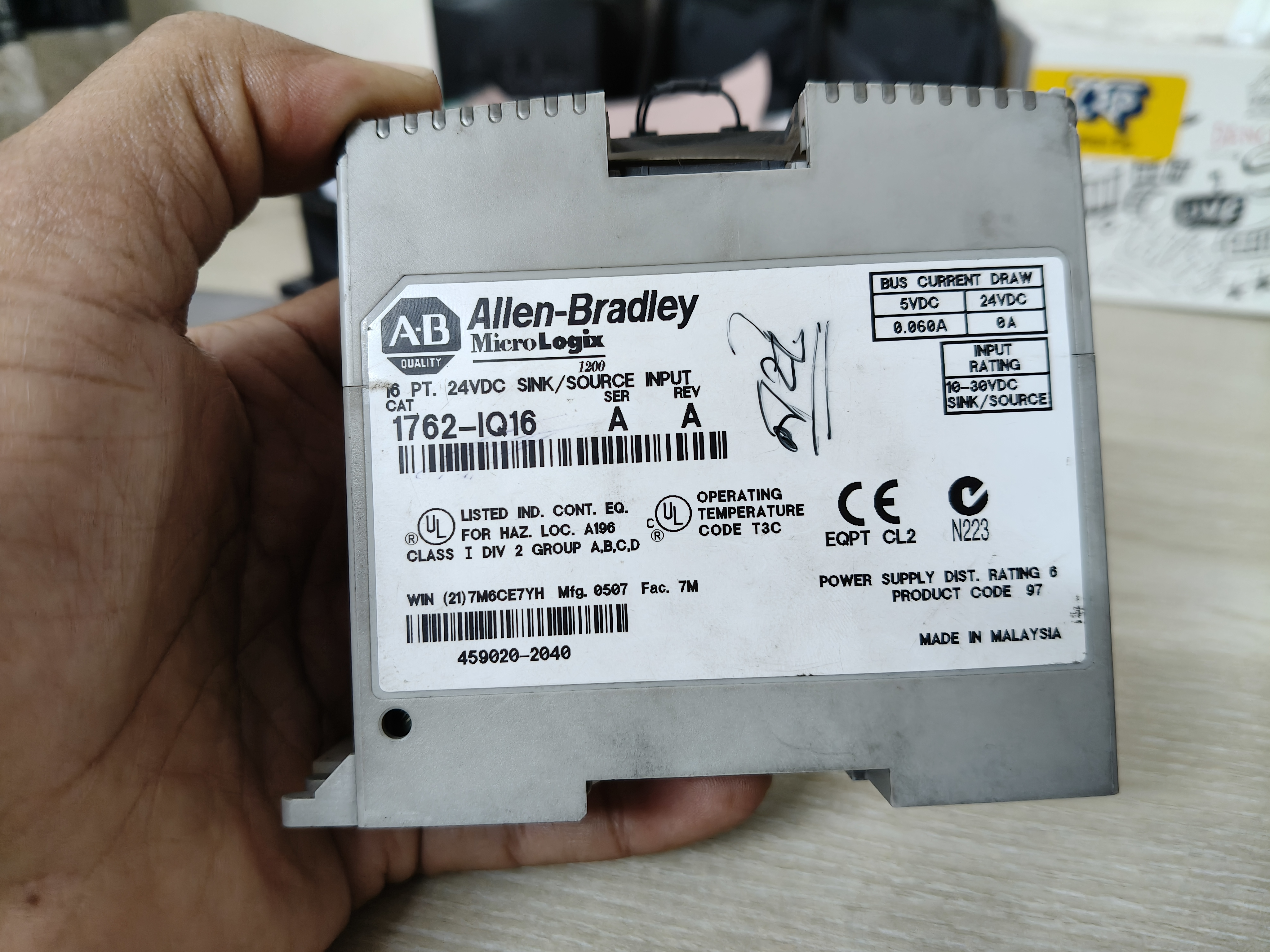
Thumbnail Photo(Allen-Bradley MicroLogix 1762-IQ16 PLC input module)
This module is a product from the MicroLogix series by the Allen-Bradley brand. Its model number is 1762-IQ16. The module features a total of 16 digital input points, labeled from IN0 to IN15. Through these inputs, signals from various sensors, push buttons, limit switches, and other digital sources can be sent to the PLC. Based on these input signals, the PLC follows a programmed sequence to control various machine operations. The model number provides insight into the module's functionality; for instance, the digits at the end of the model number indicate the number of inputs.
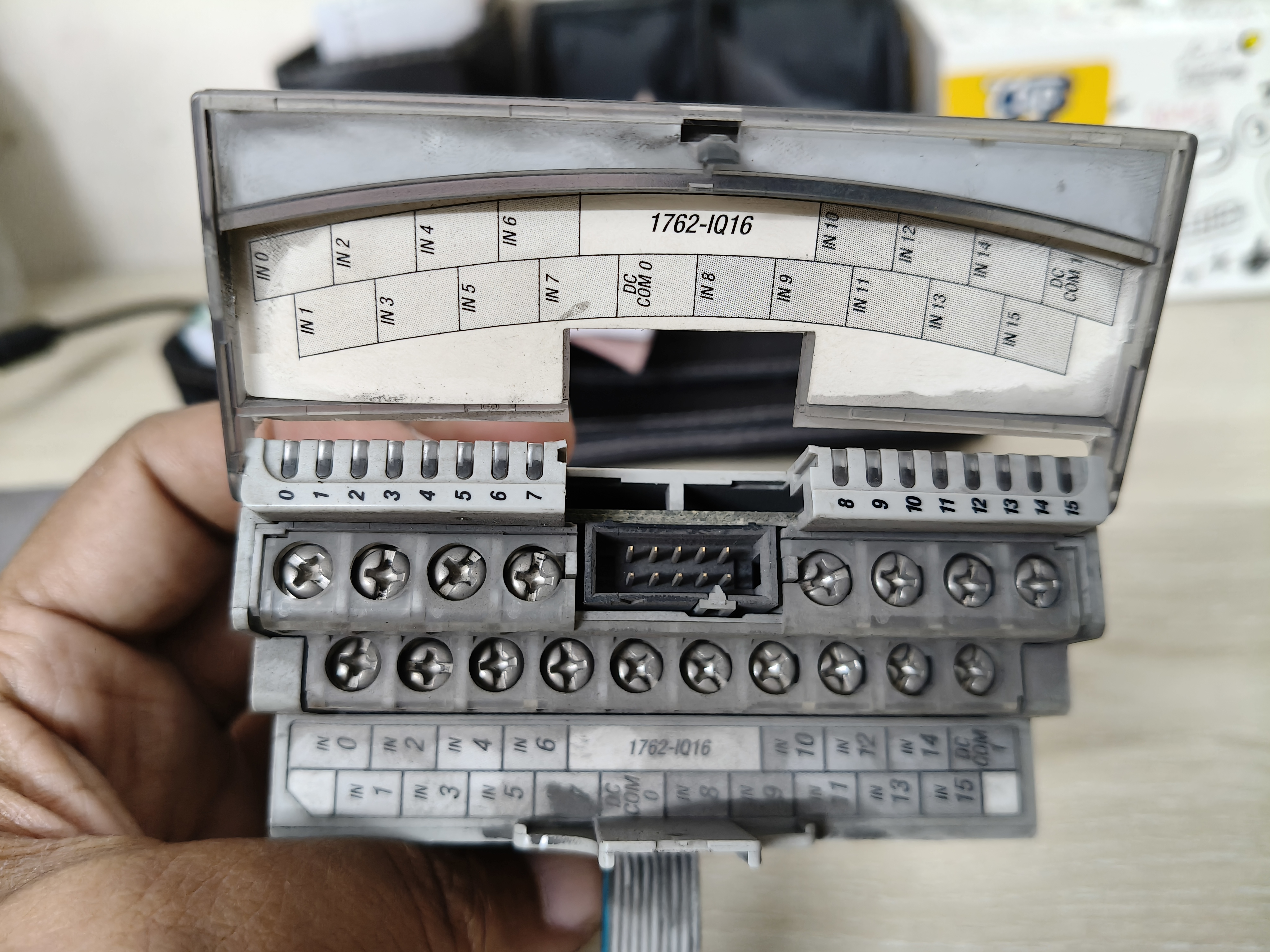
Controlling Diagram of the Allen-Bradley MicroLogix 1762-IQ16 PLC input module
The module label indicates that it is designed for a 24V DC input signal. It has an input rating of 10–30V DC and supports both sink and source input configurations. Consequently, by following the correct wiring procedure, it can be used with various types of industrial sensors and switches. However, when configuring sink or source connections, it is essential to ensure that the sensor type, common terminal, and circuit polarity are correctly matched. Terminal connections can be made by referring to the diagram provided on the device's nameplate.
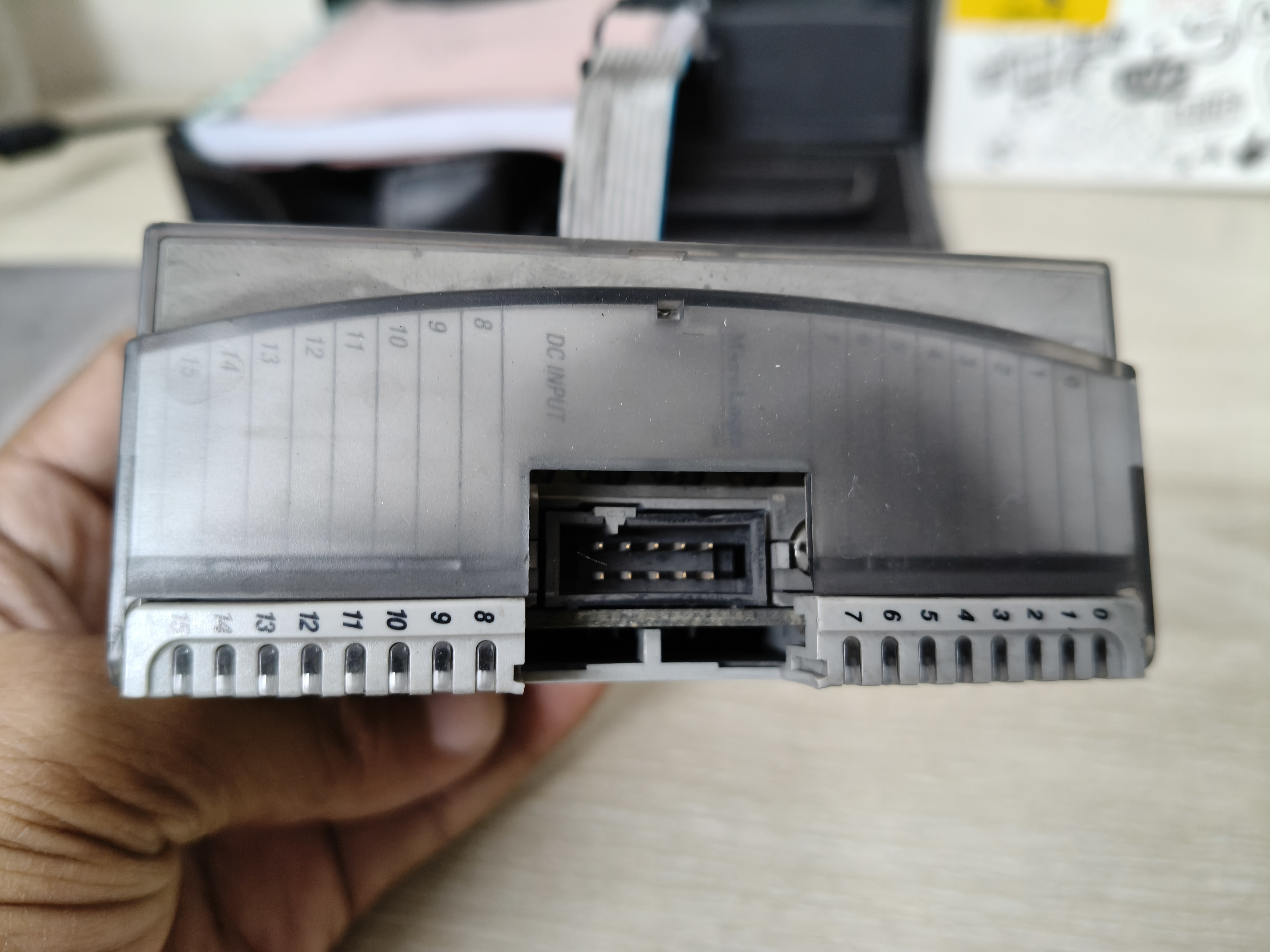
VGA Slot connection unit
In the image, the front section of the module shows terminals numbered 0 through 15, along with a 'DC COM' label. These terminals are used for input signals and common connections. The connector located in the middle is used to establish a connection with the PLC. The module also specifies a 5V DC bus current of 60 mA and a 24V DC bus current of 0 A; this means it draws a specific amount of current from the PLC's 5V backplane. An electronic switching power supply is used to provide power to the device. I wrote a post about switching power supplies a few days ago.
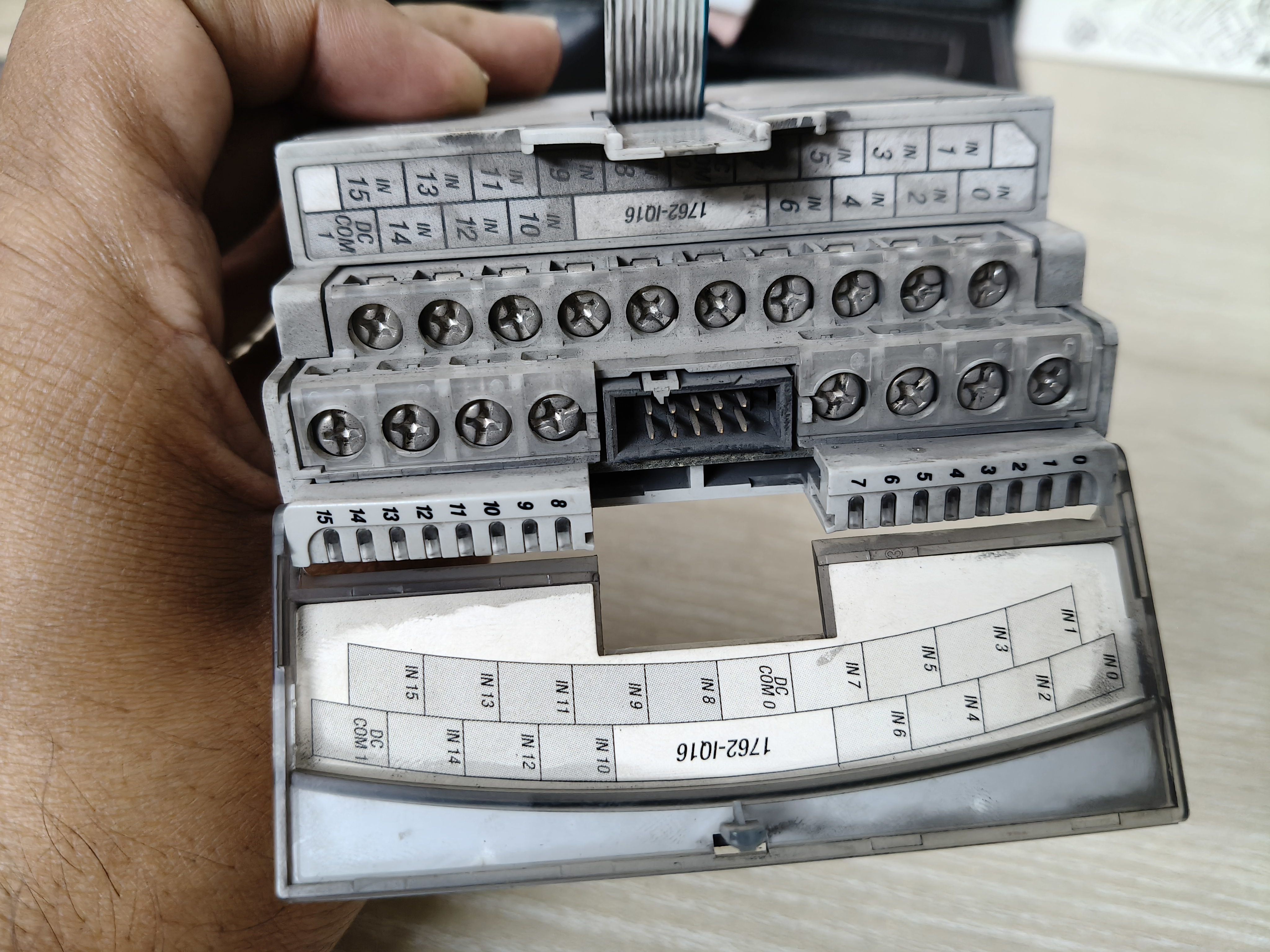
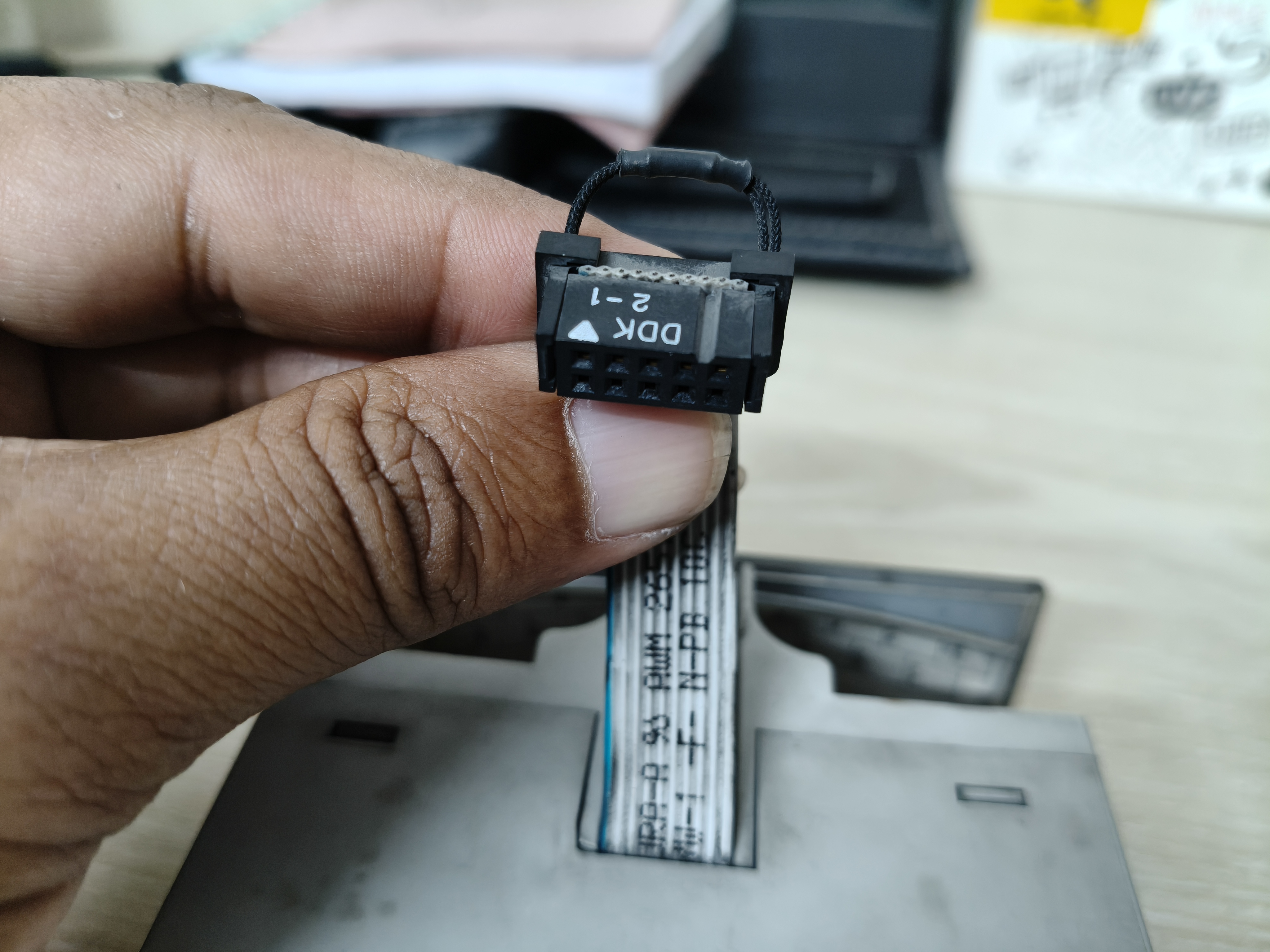
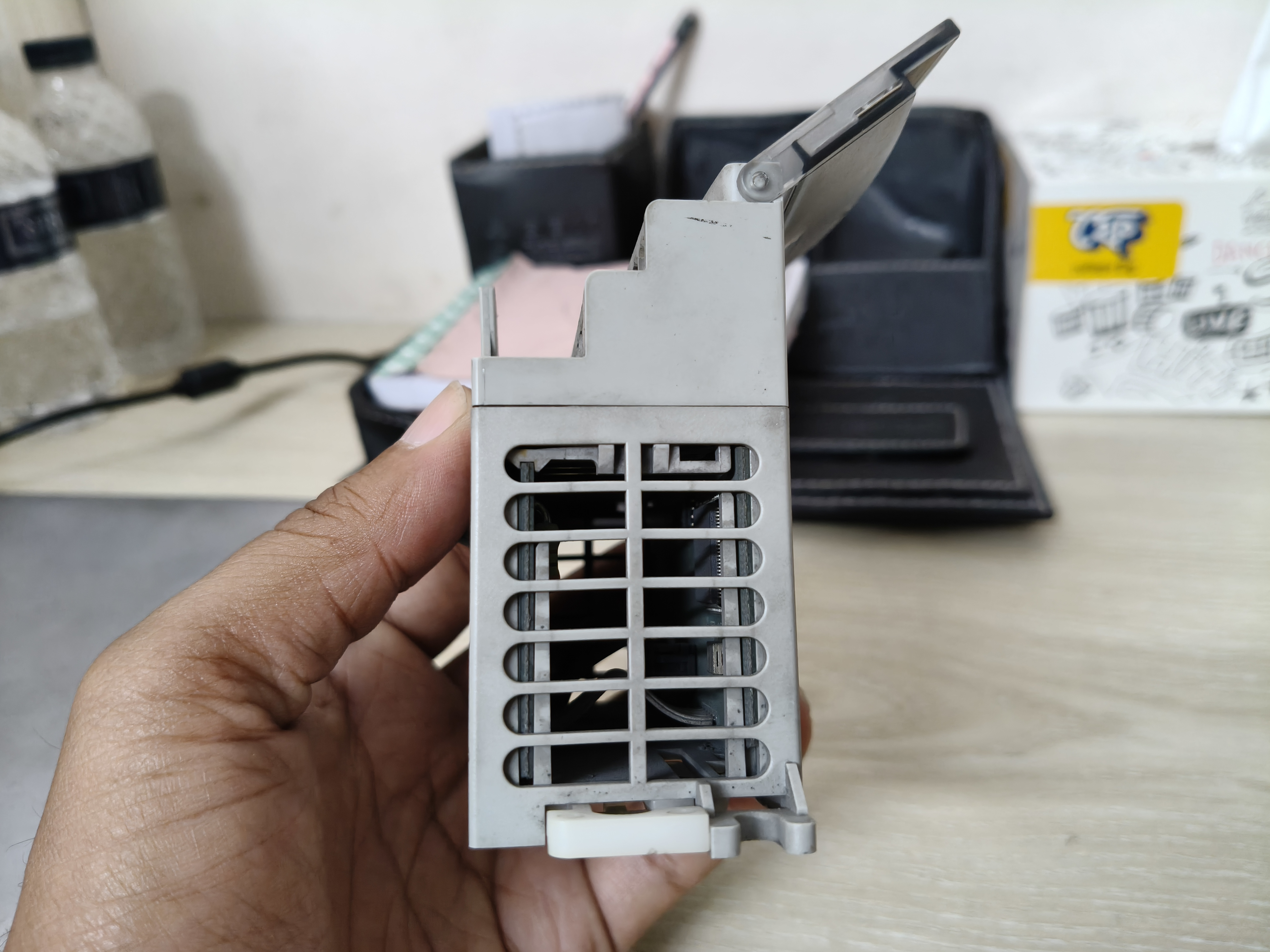
Different part of the Allen-Bradley MicroLogix 1762-IQ16 PLC input module
In industrial settings, such modules play a vital role in production lines, motor control systems, conveyors, packaging machinery, and various automated control systems. For instance, when a limit switch is activated, its signal is transmitted to a PLC (Programmable Logic Controller) via this module. Based on its programmed logic, the PLC can then issue commands—such as stopping a motor, triggering an alarm, or initiating the next stage of a process. These devices are essential for enhancing production efficiency within manufacturing facilities.
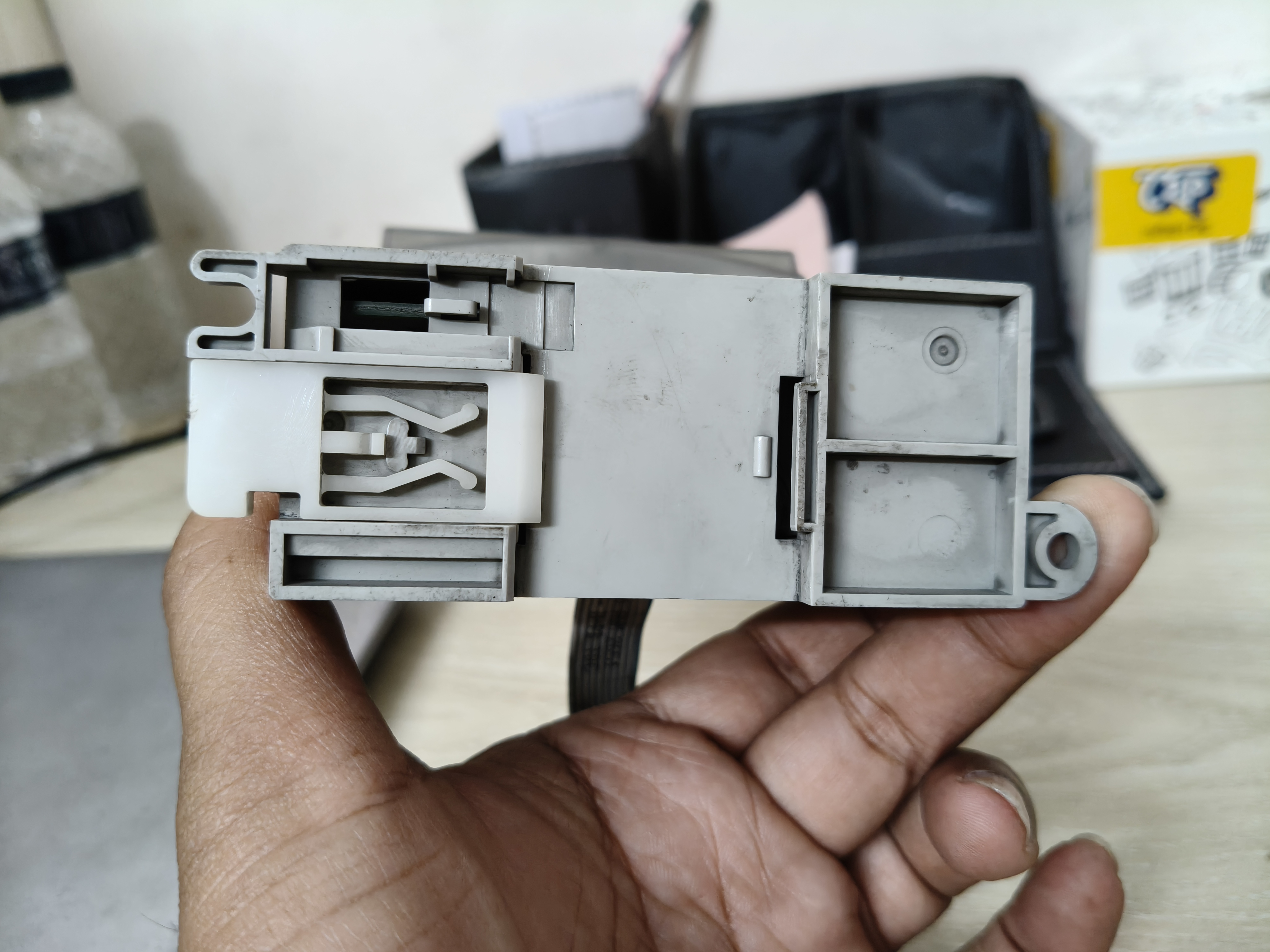
Base for mounting on a panel
In my view, having a solid understanding of PLC input modules is essential for an electrical engineer. It is important to note that these are not output modules; therefore, they cannot be used to directly drive motors or other types of loads. Through proper wiring, an appropriate power supply, and PLC programming, these modules help make industrial automation systems more reliable and efficient. PLC programming is a subject I am particularly passionate about, so I would like to share some insights on it with you today.
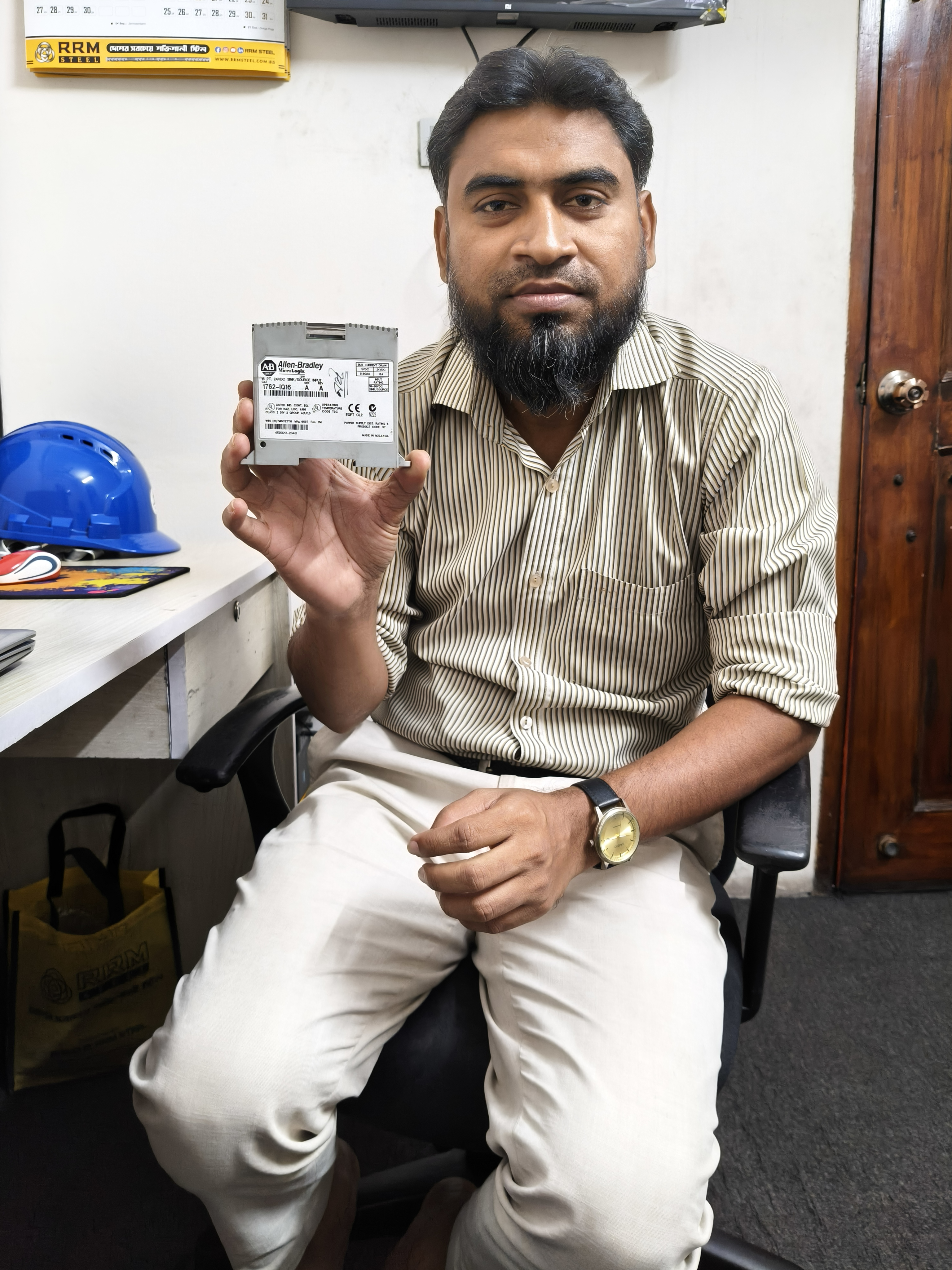
My Selfie



This is my X share link:
https://x.com/mahadih83660186/status/2114613570478690586