Charger Fan Repair Power Supply Change.
Assalamu alaikum, everyone. I am @imranhassan from #Bangladesh
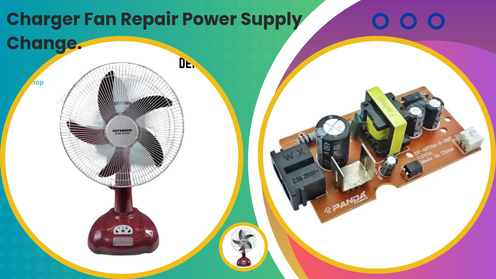
A few days ago, a charger fan came to me for repair. The customer's problem was that there was no power coming to the charger fan. And after the battery died, the fan stopped moving through the battery. So let's open this fan today and see what the problem is here.
Step -01
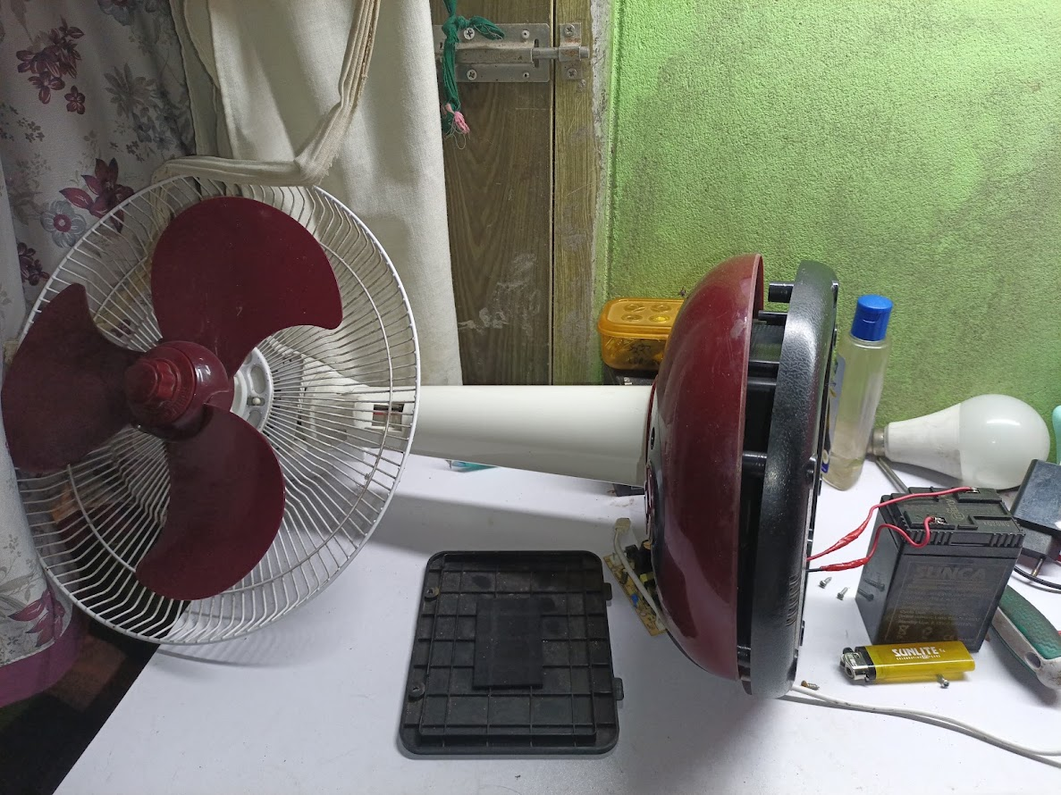
First, you can see that I have removed the battery cover from the fan body cover and taken out the battery.
Step -02
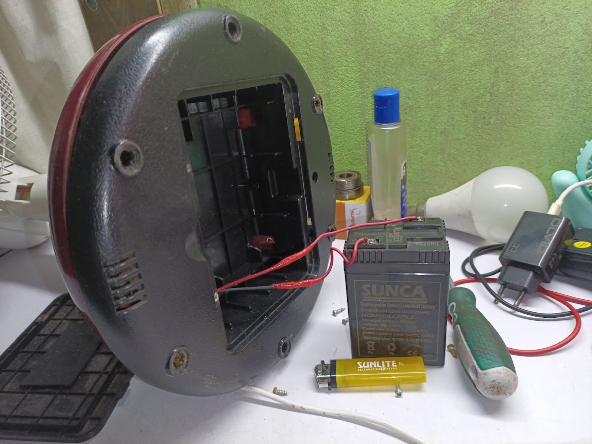
Since the battery does not have a clip here, I have to remove the solder and first measure whether there is any charging line coming to the battery.
Step -03
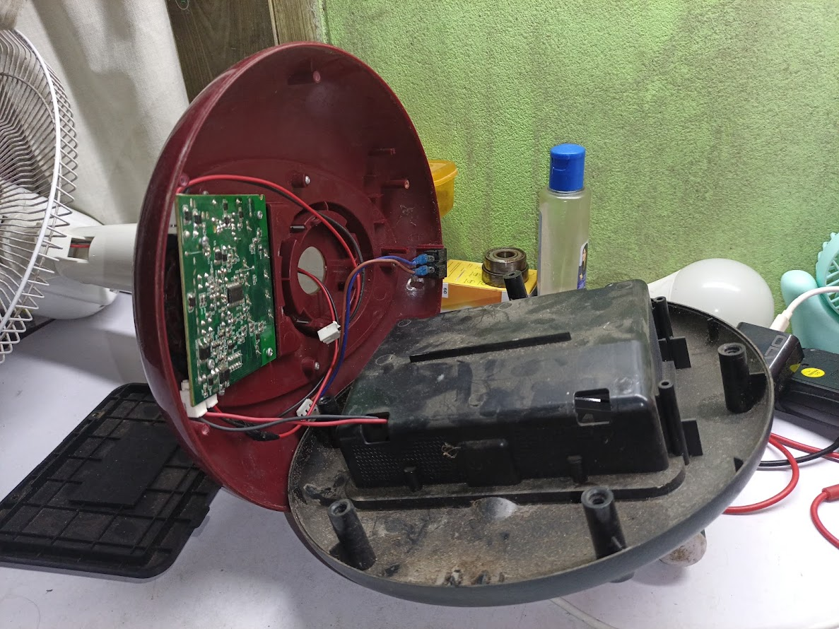
I measured the battery, and there was no charging line coming to the battery, so I opened the entire fan cover, and you can see the controlling circuit inside.
Step -04
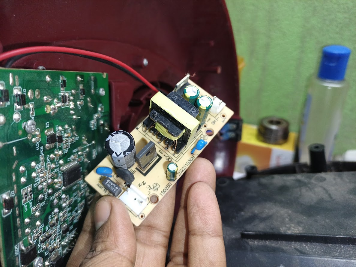
Now the circuit that you can see in my hand is basically the power supply circuit, which is used to run the entire fan. From this circuit, the voltage goes to the controlling circuit, the battery is charged through the controlling circuit, and the fan is powered.
Step -05
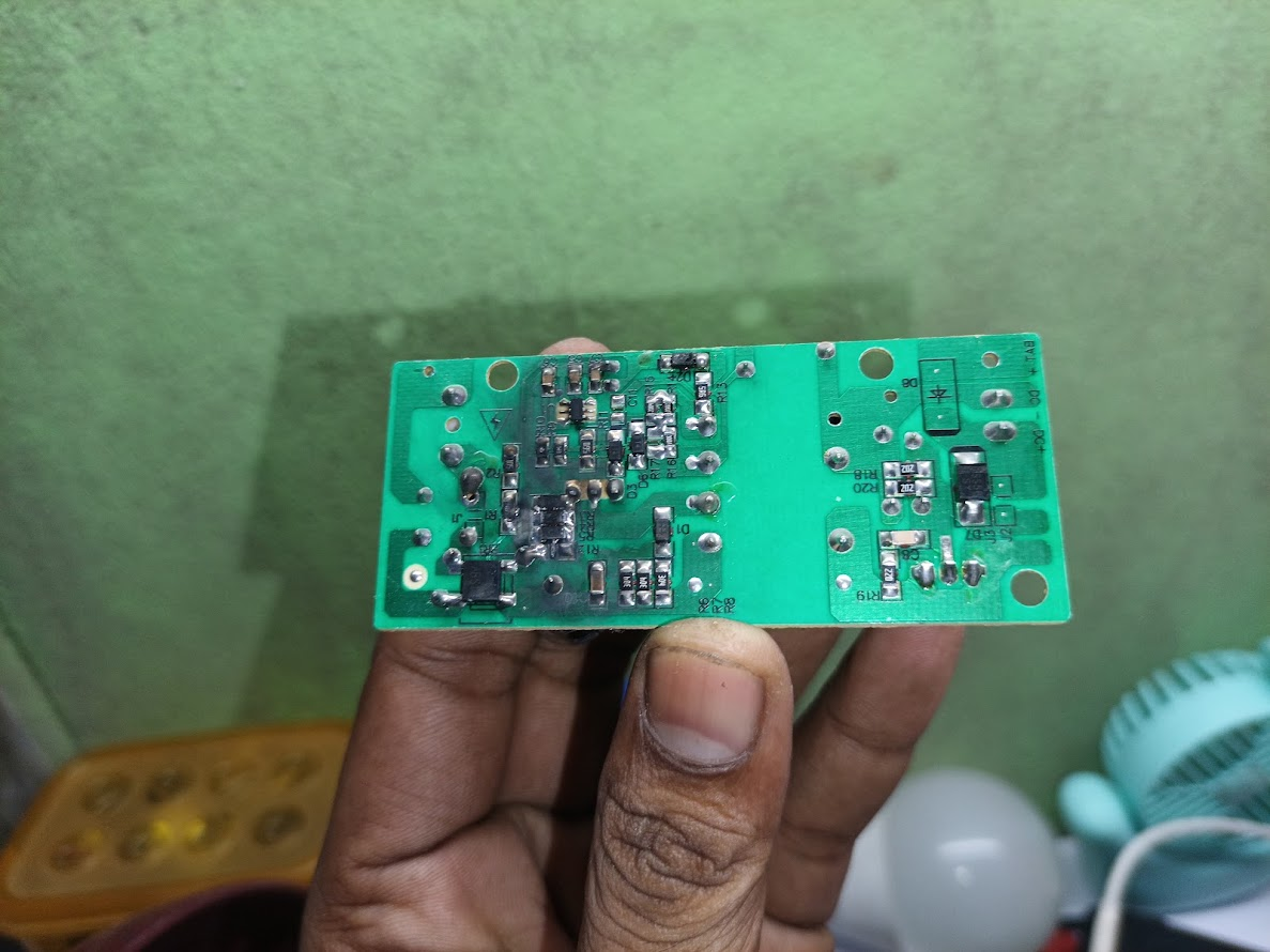
After reversing the power supply circuit, you can see that several resistances and MOSFETs have fallen and turned black. This means that this SMPS circuit is no longer repairable. This circuit is damaged, so it needs to be changed.
Step -06
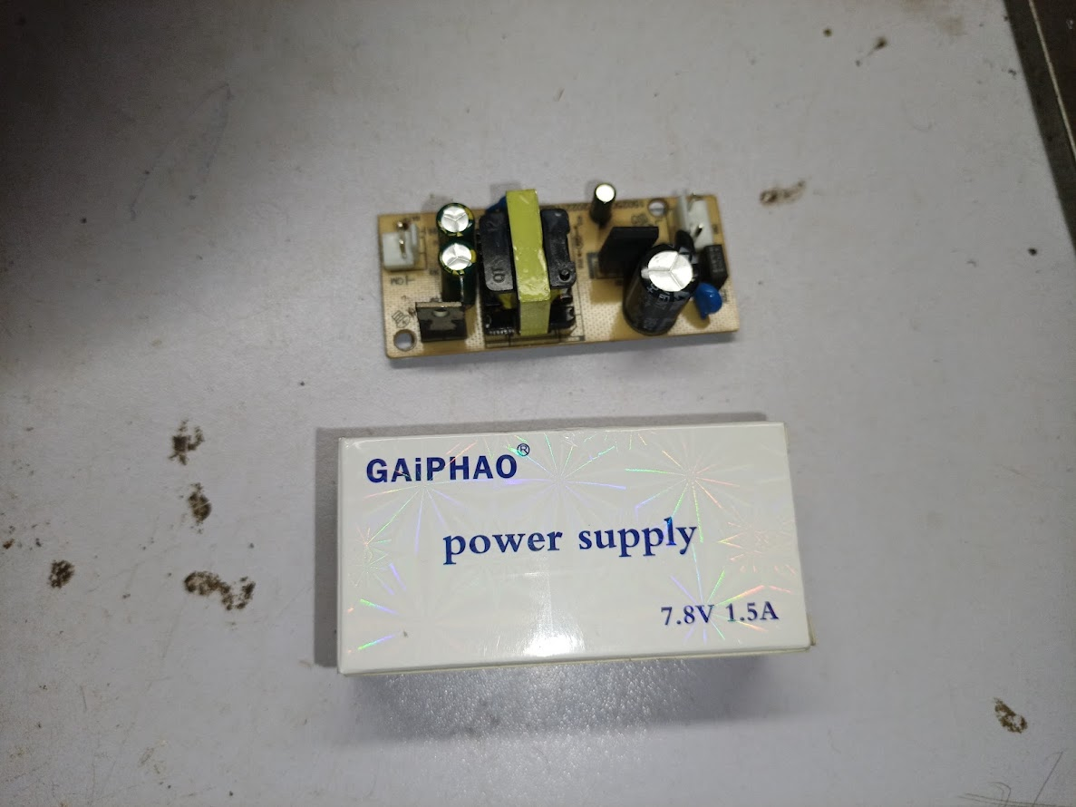
Now you can see a new white box here. Inside this box is a new power supply from a Chinese GPO company. Let's open it.
Step -07
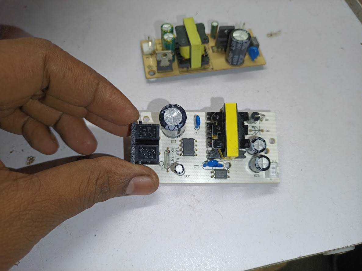
After opening it, you can see a 7.5-voltage power supply, which is basically a 6-volt control circuit and an ideal power supply for charging the battery. Since it is Chinese, it does not match my previous circuit, so I have to modify it.
Step -08
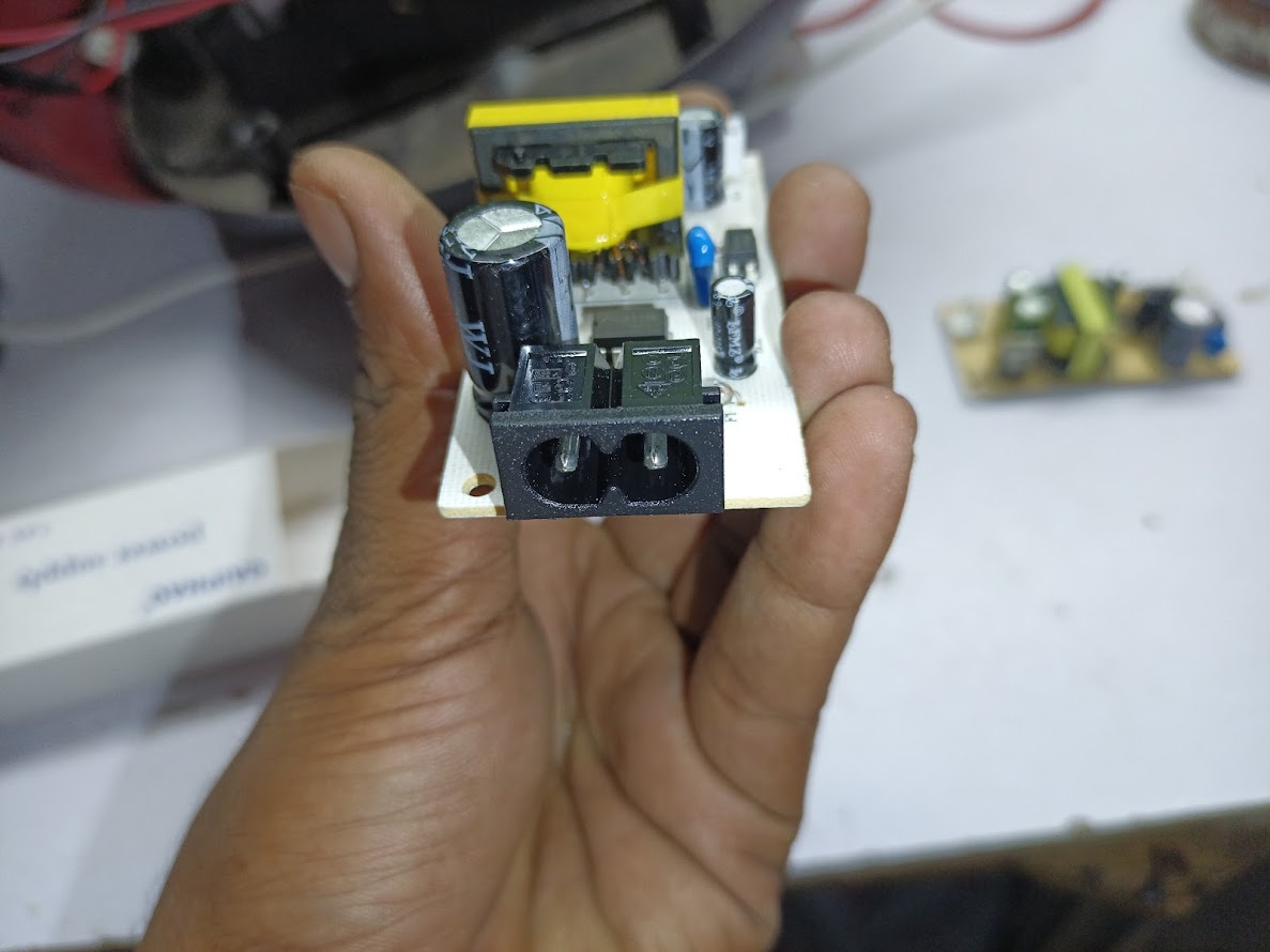
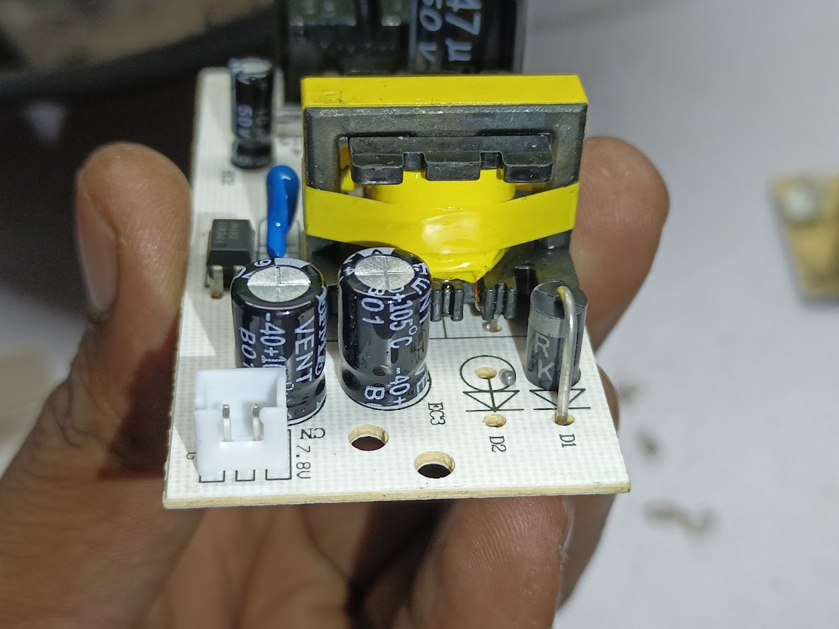
I am now showing you the circuits in reverse order. Its input voltage and output voltage. There is an AC card for the 220-volt AC power supply and a small clip socket for the 12-volt output DC.
Step -09
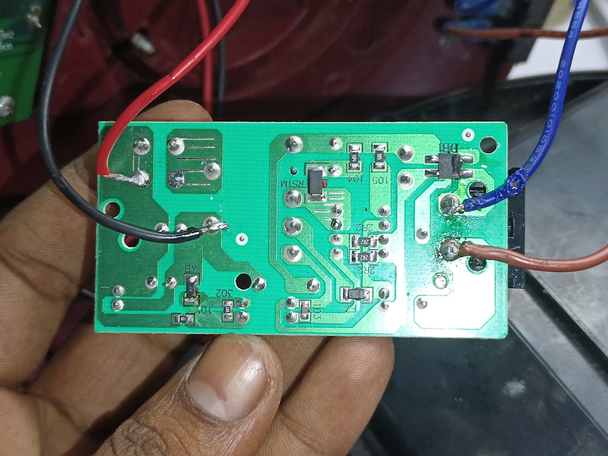
In this part, you can see the modification. Here I could not make any connection with the clip because the clip of the previous circuit does not match the new circuit clip, so I have to make the input and output match and fold it. This way it is also very strong.
Step -10
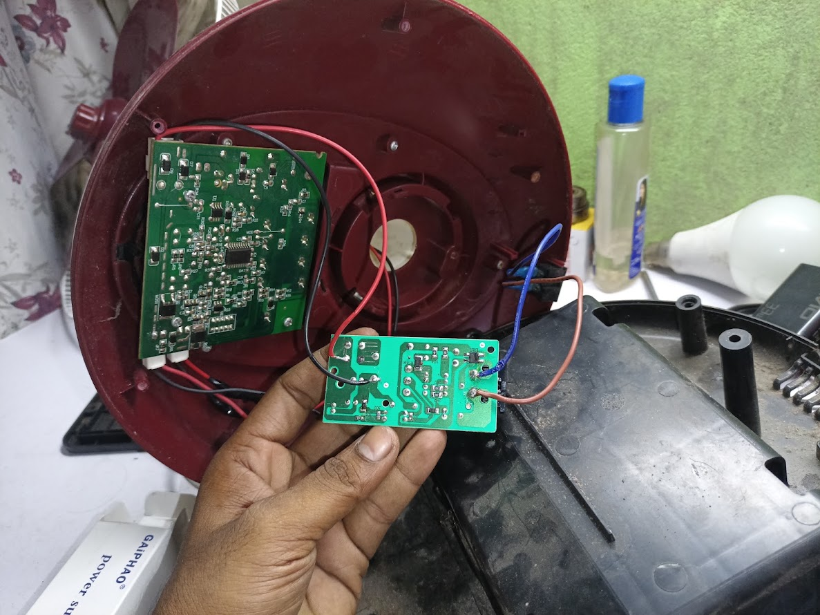
Now you can see that the AC input voltage and 12-volt DC output voltage are connected and connected to the controlling circuit.
Step -11
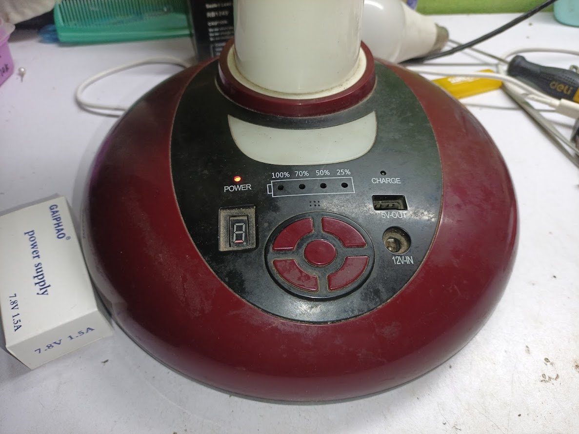
Now after giving the 220-volt AC input voltage, you can see that a red light on my fan is indicating that the power line has now come to this fan. I couldn't show any pictures in step 12 because I made a short video that shows the fan fully powered up and running. You can watch the video if you want.
| Video Tutorial: To better understand the practical part of this tutorial, you can watch the video below. |
|---|

✅ CC: My friend @rmm3
| Photography Details | 📱 Device: Walton Xanon90 | 📍 Location: Narayanganj, Bangladesh | 📷 Captured By: @imranhassan |
|---|
High-Yield Curation by @steem-seven
Your content has been supported!
| Vote Witness @seven.wit | Meet Speak on Steem |
|---|---|---|
We are the hope!
Your skills as a technician are great.Good luck to you.
Thank you very much, dear brother, for coming to my community post and commenting.