How to Test a Bridge Rectifier with a Multimeter
- Introduction
A bridge rectifier is an important part of many electronic power supplies. It converts AC voltage into pulsating DC voltage, which can then be filtered and regulated by the rest of the circuit.
Knowing how to test a bridge rectifier with a multimeter is a useful skill for diagnosing faulty adapters, chargers, power supplies, and other electronic equipment.
- What Is a Bridge Rectifier?
A bridge rectifier is a circuit made from four diodes connected in a bridge configuration.
It usually has four terminals:
~ AC input
~ AC input
- DC positive output
− DC negative output
Some bridge rectifiers are available as a single packaged component, while others are built using four separate diodes.
- What Does It Do?
The main job of a bridge rectifier is to convert AC into full-wave pulsating DC.
During one half-cycle of the AC waveform, one pair of diodes conducts. During the opposite half-cycle, another pair conducts.
As a result, current through the load continues in the same direction during both halves of the AC cycle.
A capacitor is often connected after the rectifier to smooth the pulsating DC into a higher, more stable DC voltage.
- Important Specifications
When replacing a bridge rectifier, important specifications can include:
Maximum repetitive reverse voltage
Average or continuous forward current rating
Surge current capability
Forward voltage
Operating temperature range
Package type and pin configuration
These specifications vary between bridge rectifier models. The exact rating should always be checked against the manufacturer's datasheet.
- How Does a Bridge Rectifier Work?
Consider an AC source connected to the two ~ terminals.
When one AC terminal is positive relative to the other, two internal diodes conduct and send current toward the + terminal and back through the − terminal.
When the AC polarity reverses, the other two diodes conduct.
Therefore, the output polarity remains the same even though the input polarity continuously changes.
This is called full-wave rectification.
- How to Test a Bridge Rectifier with a Multimeter
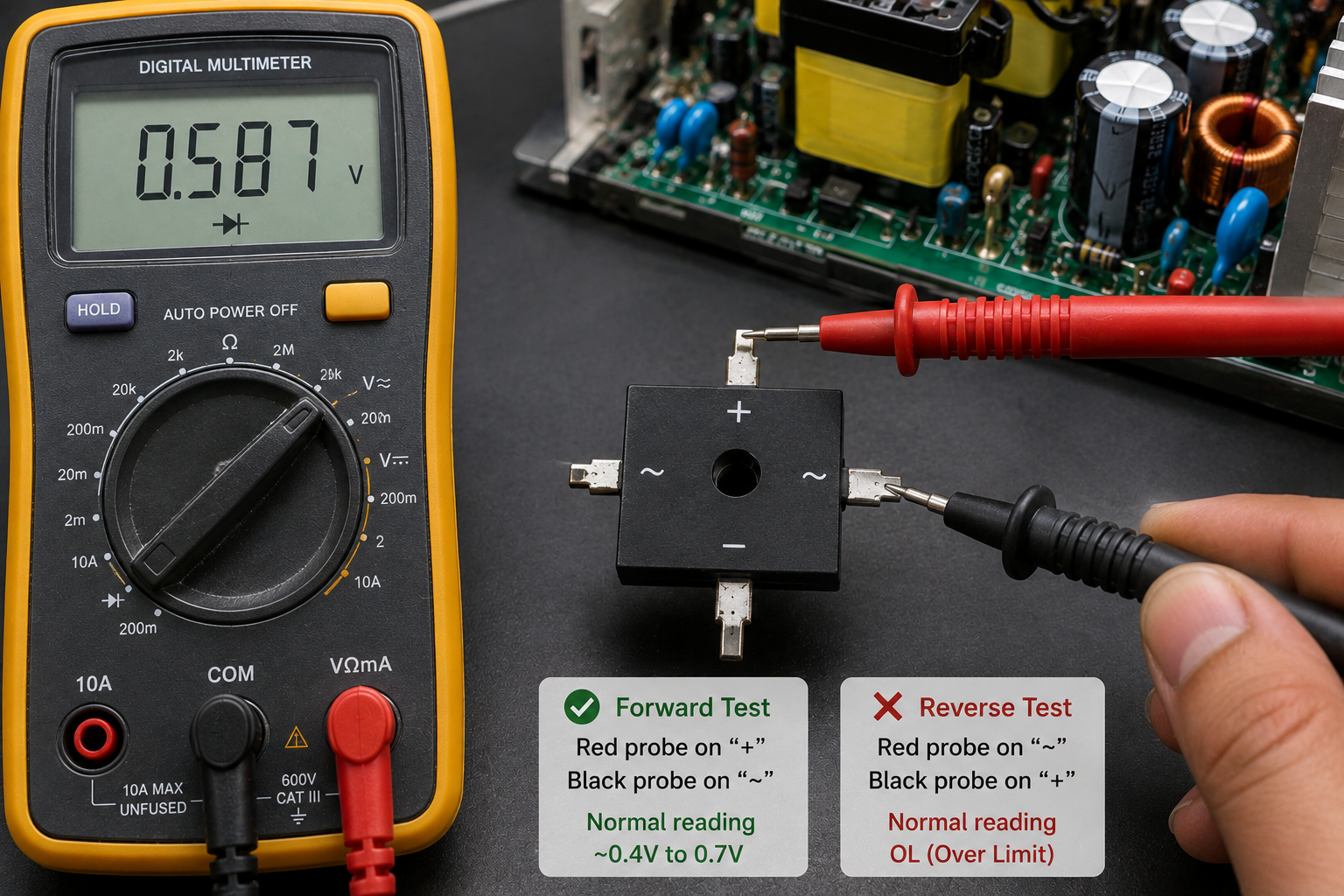
A digital multimeter with a diode-test function is normally the most useful tool.
First:
- Disconnect the equipment from the power source.
- Make sure dangerous stored voltage has been safely discharged.
- If possible, isolate the bridge rectifier from surrounding circuitry.
- Set the multimeter to diode-test mode.
- Test the rectifier terminals according to its internal diode arrangement or datasheet.
For a typical four-terminal bridge, each ~ terminal has a diode path toward + and another diode path from − toward that ~ terminal.
The exact probe combinations depend on the bridge's pin arrangement, so the printed terminal markings and datasheet should be used rather than assuming a particular physical pin order.
- Expected Readings
A healthy silicon diode junction commonly produces a forward voltage reading in the approximate range of several hundred millivolts, often around 0.5–0.8 V under typical multimeter test conditions.
However, this is an approximate behavior, not a universal specification.
In the reverse direction, a normal diode junction should generally show OL or a very high reading on a standard digital multimeter.
For a bridge rectifier:
Forward direction → measurable diode drop
Reverse direction → typically OL
Both directions conducting → possible shorted junction
OL in both directions where conduction should occur → possible open junction
The actual reading can vary with the diode material, meter, test current, temperature, and component design.
- How to Identify a Good Bridge Rectifier
A bridge rectifier is generally considered electrically healthy when:
Each internal diode junction conducts in the expected forward direction.
Reverse-biased junctions do not show normal forward conduction.
There is no obvious short circuit between terminals that should be isolated.
The measured behavior matches the manufacturer's internal diode configuration.
- How to Identify a Faulty Bridge Rectifier
Common failure patterns include:
Shorted diode:
The meter may show very low resistance or an unusually low diode-test reading in both directions.
Open diode:
The meter may show OL in both directions where one direction should conduct.
Multiple damaged junctions:
Several terminal combinations may show abnormal readings.
A bridge rectifier that fails can cause symptoms such as a blown fuse, excessive input current, low or missing DC output, or a short circuit on the power-supply input.
- Common Mistakes
One common mistake is testing a bridge rectifier while it is still connected to a complicated circuit.
Other components can create alternative current paths and produce misleading readings.
Another mistake is assuming that every bridge rectifier has the same physical pin order.
Always identify the +, −, and ~ terminals from the component marking or datasheet.
Do not perform resistance or diode testing on a powered circuit.
- Practical Repair/Use Example
Imagine a mains-powered switching power supply that immediately blows its input fuse.
After safely disconnecting the power supply and dealing with stored energy, the bridge rectifier can be isolated and tested.
If one internal diode is shorted, the rectifier can create an abnormal current path across the AC input. This may cause the fuse or another protective component to operate.
If the bridge is confirmed faulty, the replacement should have suitable voltage, current, surge, temperature, and package ratings for the original circuit.
- Safety Notes
Bridge rectifiers are frequently used in mains-powered equipment.
A rectifier connected to AC mains can involve lethal voltage. Large capacitors after the rectifier can also retain dangerous energy after the equipment is unplugged.
Never test a live mains circuit with the multimeter set to diode or resistance mode.
Only work on mains equipment if you understand electrical safety and have the appropriate tools and procedures.
🔧 Practical Example
A 230 V AC power supply has no DC output and its input fuse has failed.
After disconnecting the equipment and safely handling the stored charge, the technician checks the bridge rectifier with the diode-test function.
The four internal diode paths are checked individually according to the rectifier's +, −, and ~ markings.
If one junction conducts in both directions, or remains open in both directions when conduction should occur, the bridge rectifier is a strong suspect.
Before installing a replacement, the technician should also check for other failed components, because a shorted MOSFET or another primary-side fault may have caused the bridge rectifier failure.
⚠️ Important Notes
A bridge rectifier should not be judged only from one multimeter reading.
The surrounding circuit can affect measurements when the rectifier is tested in-circuit.
Also, a replacement rectifier should never be selected only because its physical size is similar. Its electrical ratings and pin configuration must be suitable for the circuit.
For accurate repair work, compare the original component with its datasheet whenever possible.
🇧🇩 বাংলা সংক্ষেপ
Bridge Rectifier সাধারণত AC voltage কে full-wave pulsating DC-তে রূপান্তর করে। এতে সাধারণত চারটি diode-এর কাজ একসাথে থাকে।
Multimeter-এর diode mode দিয়ে এর internal diode junction পরীক্ষা করা যায়। সাধারণভাবে forward direction-এ কিছু voltage drop দেখা যায় এবং reverse direction-এ OL দেখা যায়।
যদি কোনো junction দুই দিকেই conduct করে, তাহলে সেটি short হতে পারে। আবার যেখানে conduction হওয়ার কথা সেখানে দুই দিকেই OL থাকলে diode open হতে পারে।
Mains power supply-এর bridge rectifier পরীক্ষা করার সময় অবশ্যই নিরাপত্তার বিষয়টি গুরুত্ব দিতে হবে।
Conclusion
Understanding how a bridge rectifier works and how to test it with a multimeter can make power-supply troubleshooting much easier. A few systematic diode tests can help identify open or shorted internal junctions and determine whether the rectifier should be investigated further or replaced.